Advanced Optical Systems: Aberrations, Wide-Angle Imaging, and Biological Eyes
- 1. Lens Aberrations
- 2. Wide-Angle and Catadioptric Imaging Systems
- 3. Biological Eye Designs and Evolution
- Summary
1. Lens Aberrations
Even perfect lenses produce unwanted effects called aberrations due to the nature of light. These are physical limitations, not manufacturing defects.
1.1 Vignetting
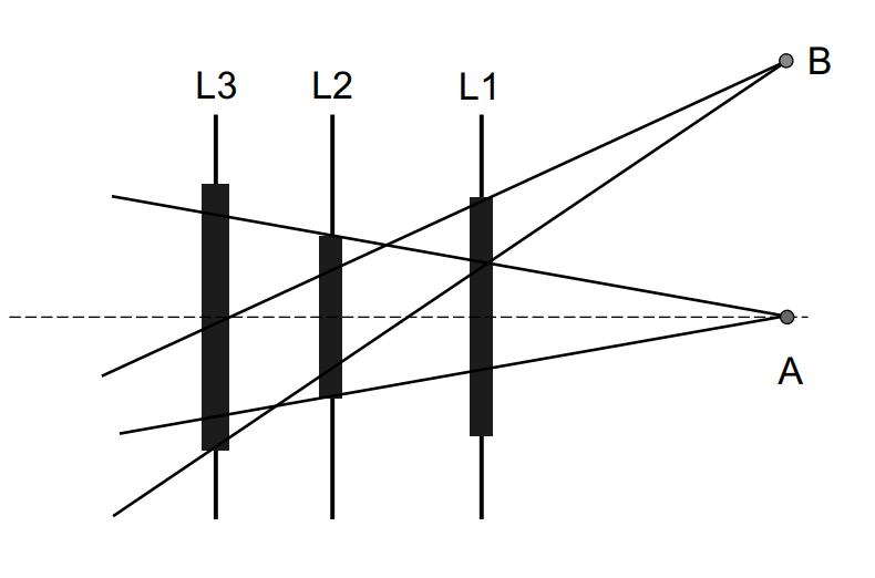
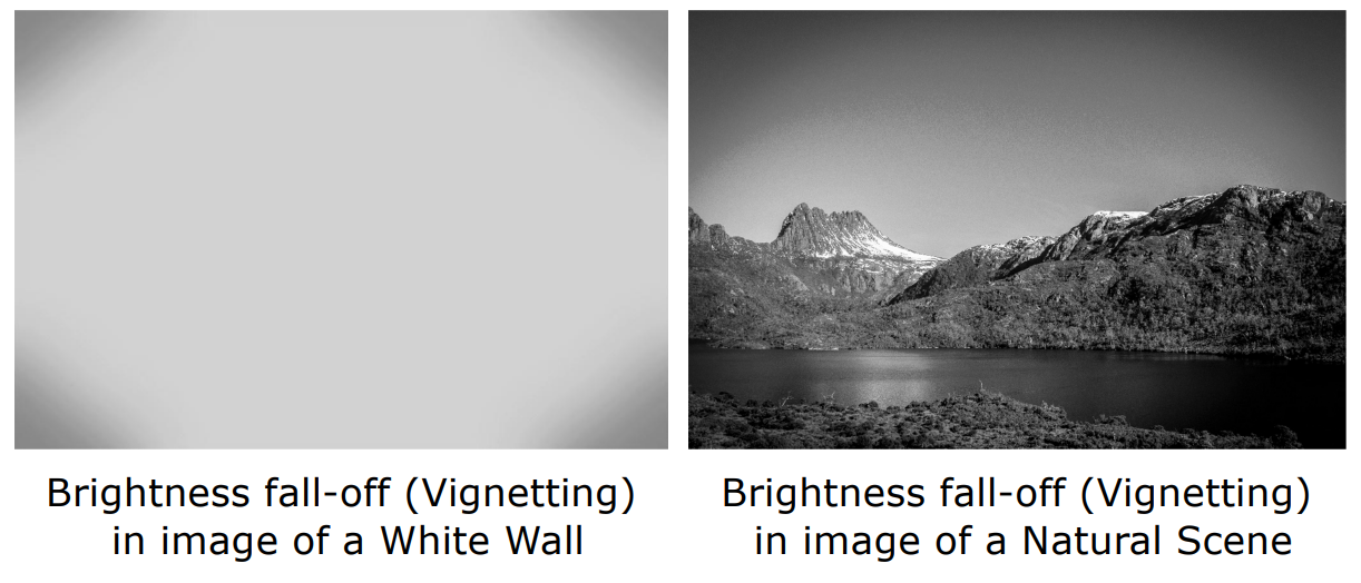
Vignetting is the darkening of image corners caused by:
- The lens body mechanically blocking oblique rays.
- A reduction in solid angle at the periphery of the image field.
The result is a gradual fall-off in brightness from the center to the corners of the image.
1.2 Chromatic Aberration
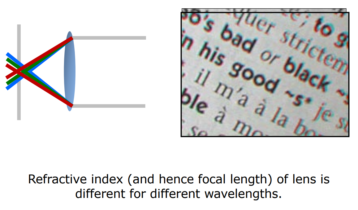
The refractive index of glass depends on the wavelength ($\lambda$) of light. In the visible spectrum (400 nm — 700 nm), blue light (400 nm) bends more than red light (700 nm). This causes different colors to focus at different planes, producing color fringing at object edges.
flowchart LR
    A["White Light<br/>400-700 nm"] --> B["Lens"]
    B --> C["Blue Focus<br/>(shorter focal length)"]
    B --> D["Red Focus<br/>(longer focal length)"]
    C --> E["Color Fringing at Edges"]
    D --> E

    style A fill:#1a1a2e,stroke:#fff,color:#fff
    style B fill:#16213e,stroke:#4cc9f0,color:#fff
    style C fill:#1a1a2e,stroke:#4361ee,color:#4361ee
    style D fill:#1a1a2e,stroke:#e94560,color:#e94560
    style E fill:#0f3460,stroke:#f72585,color:#fff
1.3 Geometric Distortions
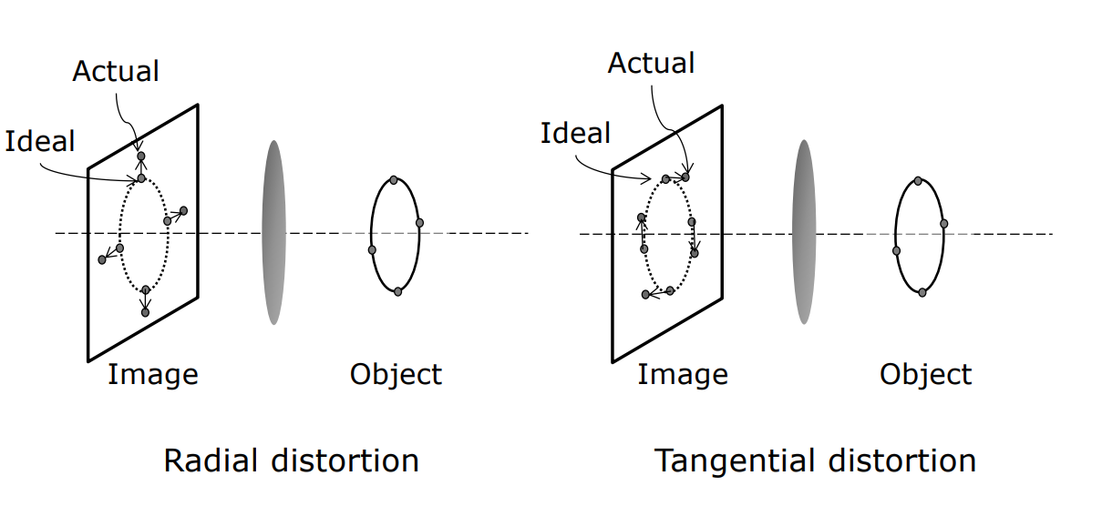
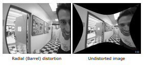
Radial distortion (barrel distortion) causes the image to bulge outward. These effects can be corrected in computer vision software through inverse mapping — a calibration process that models the distortion parameters and inverts them.
| Distortion Type | Effect | Visual |
|---|---|---|
| Barrel (Fıçı) | Lines bow outward from center | 👁️ Wide-angle look |
| Pincushion (İğne Yastığı) | Lines bow inward toward center | 🔍 Telephoto look |
Key Insight: Distortion is deterministic and correctable — knowing the lens model allows precise geometric rectification.
2. Wide-Angle and Catadioptric Imaging Systems
These systems are designed to overcome the limitations of standard perspective projection and are strategically important in security and robotics.
2.1 Fisheye Lenses
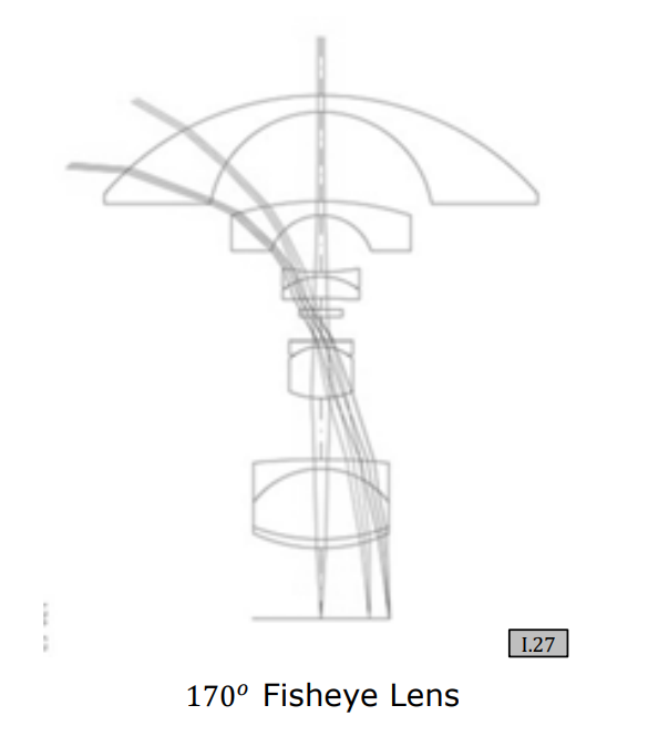
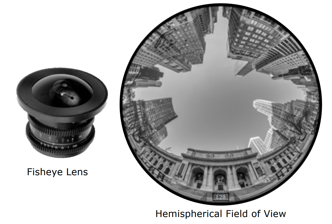
Fisheye lenses use meniscus elements to achieve extreme light bending. The single viewpoint constraint is critical for software rectification — all rays must appear to converge at a single optical center for the image to be mathematically unwrapped.
2.2 Catadioptric Systems
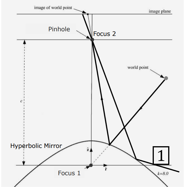
Catadioptric systems combine mirrors (catoptric) and lenses (dioptric):
| Type | Mirror Shape | Use Case |
|---|---|---|
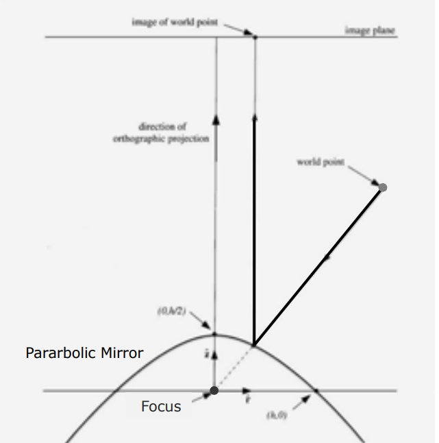
| Telescope | Parabolic | Collects parallel rays at a single point |
| Omnidirectional | Hyperbolic (convex) | Captures 360° panoramic view for surveillance |
2.3 Corneal Imaging
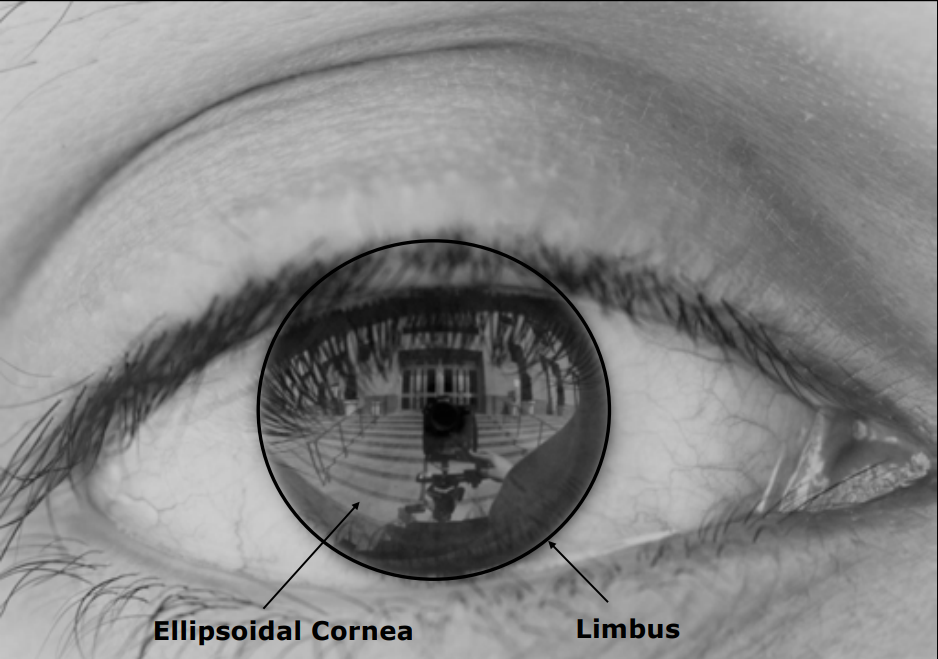
The human cornea acts as a convex mirror. Using limbus detection and corneal reflection analysis, it is possible to determine what a person is looking at (their retinal image) from a high-resolution photograph taken from outside.
flowchart LR
    A["External Camera"] -->|"High-res photo"| B["Corneal Reflection<br/>Convex mirror"]
    B -->|"Limbus detection"| C["Gaze Direction<br/>Analysis"]
    C -->|"Inverse projection"| D["Retinal Image<br/>(What person sees)"]

    style A fill:#1a1a2e,stroke:#e94560,color:#fff
    style B fill:#16213e,stroke:#4cc9f0,color:#fff
    style C fill:#0f3460,stroke:#f72585,color:#fff
    style D fill:#1a1a2e,stroke:#06d6a0,color:#fff
3. Biological Eye Designs and Evolution
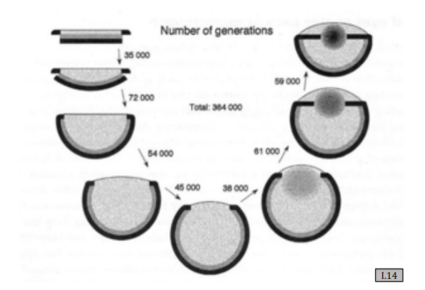
Eyes in nature represent the evolutionary perfection of image formation principles. A simulation by Nilsson demonstrated that a flat, light-sensitive epithelium could evolve into a complex eye in just 400,000 generations.
3.1 The Evolutionary Path
flowchart LR
    A["Flat Light-Sensitive Epithelium"] --> B["Curving for Directional Sensitivity"]
    B --> C["Aperture Narrowing for Sharpness"]
    C --> D["Lens Formation for Light Collection"]
    D --> E["Complex Eye"]

    style A fill:#1a1a2e,stroke:#4cc9f0,color:#fff
    style B fill:#16213e,stroke:#4cc9f0,color:#fff
    style C fill:#0f3460,stroke:#f72585,color:#fff
    style D fill:#16213e,stroke:#e94560,color:#fff
    style E fill:#1a1a2e,stroke:#06d6a0,color:#fff
3.2 Comparative Biology
| Species | Eye Type | Key Feature |
|---|---|---|
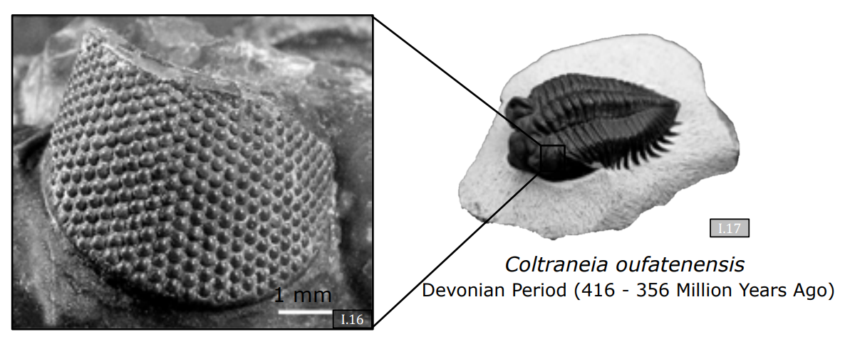
| Trilobites (400M years ago) | Compound eye | Thousands of calcite crystal lenses |
| Human | Single lens eye | Corneal bending power + crystalline lens accommodation |
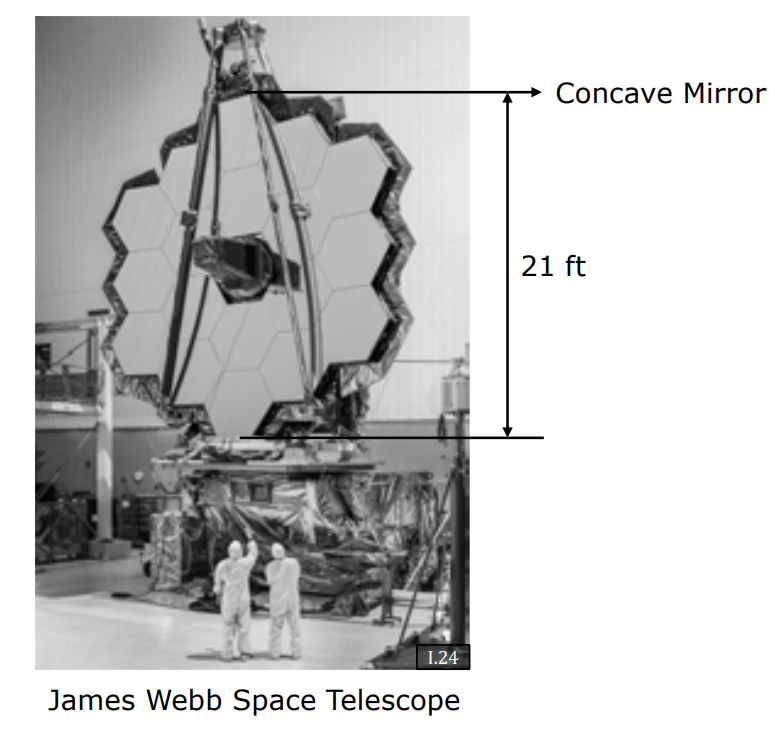
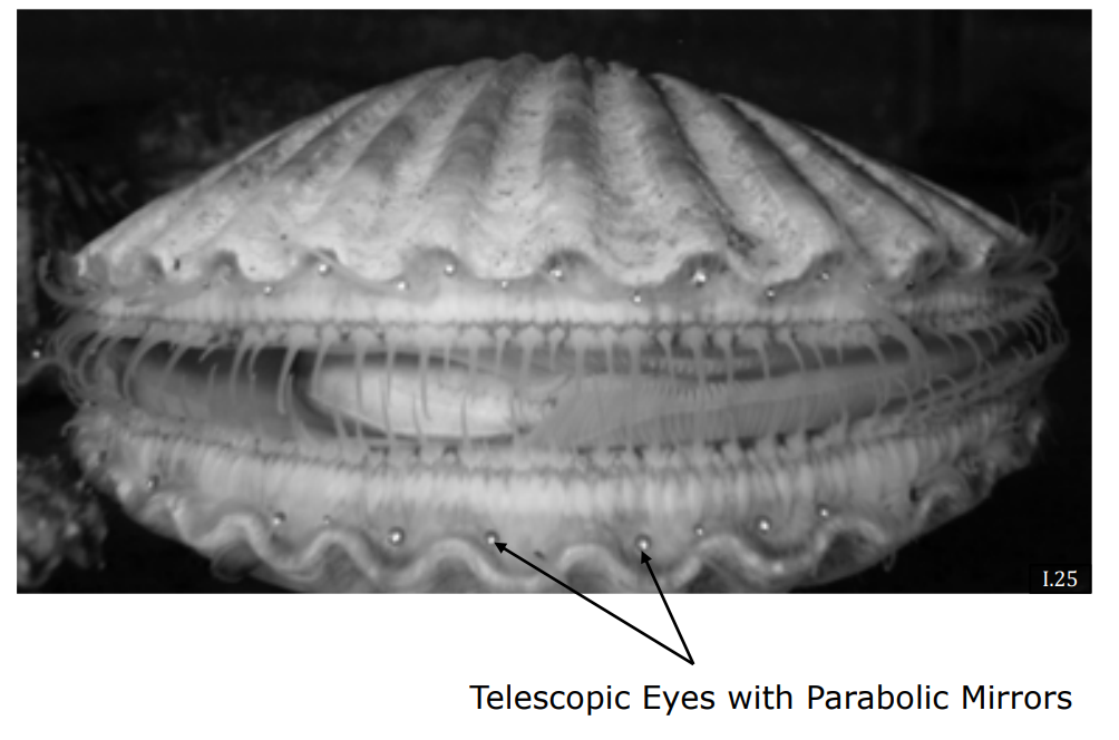
| Scallop | Multiple mirror eyes | Concave parabolic mirrors (like James Webb Telescope) |
Fascinating Fact: Trilobite eyes used calcite — a mineral that does not soften with age — as their lens material, giving them perfect vision throughout their lifespan.
3.3 The Human Eye and Accommodation
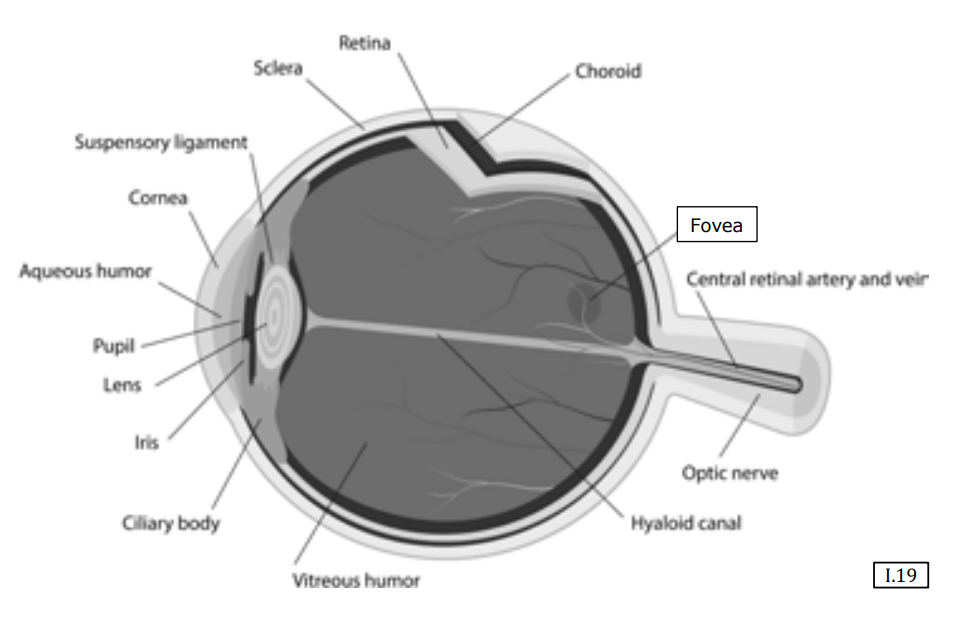
The human eye combines two optical elements:
- Cornea — Provides most of the bending power (refractive index difference between air and tissue).
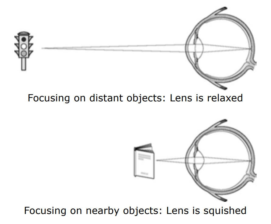
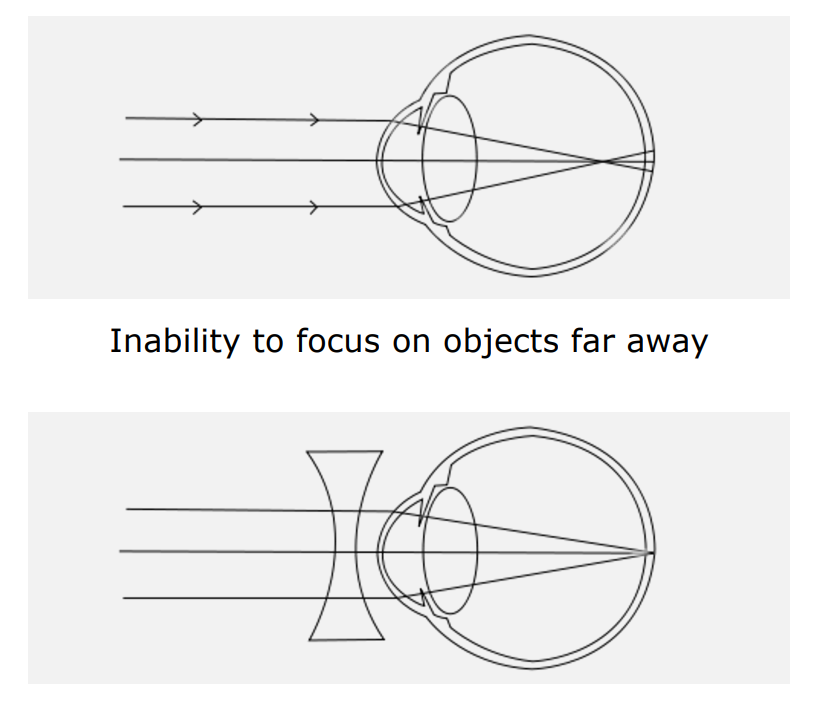
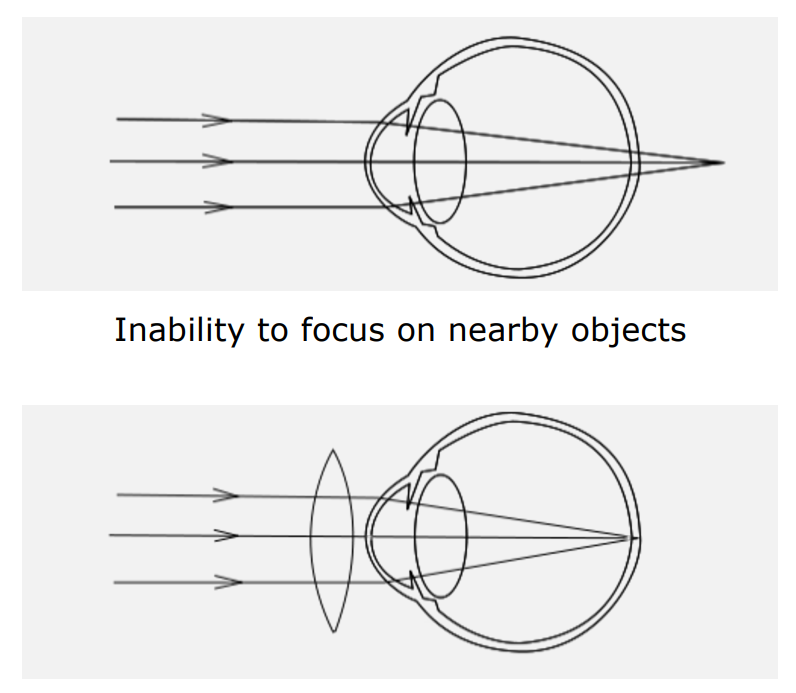
- Crystalline Lens — A fluid-filled flexible lens that adjusts shape for accommodation (focusing at different distances).
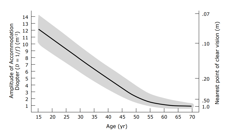
As we age, the crystalline lens hardens (presbyopia):
$$ \text{Minimum Focus Distance} \approx \begin{cases} 7 \text{ cm} & \text{at age 10} \ 10 \text{ cm} & \text{at age 20} \ 50 \text{ cm} & \text{at age 50+} \end{cases} $$
3.4 Scallop Eyes: Nature’s Mirror Telescopes
Scallops have hundreds of eyes, each using a concave parabolic mirror rather than a lens to focus light. This is the same optical principle used by the James Webb Space Telescope — a remarkable case of convergent evolution between biology and engineering.
Summary
- Aberrations (vignetting, chromatic, distortion) are unavoidable physical effects of lens systems.
- Catadioptric systems combine mirrors and lenses for specialized imaging (panoramic, telescope).
- Corneal imaging allows gaze detection from external photographs.
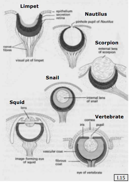
- Biological eyes evolved through a well-understood path and offer diverse optical strategies — pinhole (nautilus), compound (trilobite), refractive (human), and reflective (scallop).
- Whether an ancient trilobite lens or a modern liquid lens, image formation is the central achievement of both biological and technological evolution in understanding the 3D world on a 2D plane.